Go back
DMC2Mini Test and Intro to cnc Machining
15 aout 2025
The new Cnc DMC2 Mini is up and ready and I take time to learn some really basic G-code programming
Small and fast intro to Cnc
The "CNC" part stands for Computer Numerical Control, which refers to the use of computers to control the machine's movements and operations with a specific language know as G-code.
What is G-Code
It's a set of instructions that tells the machine what actions to perform, such as moving to a specific location, turning on or off a spindle, or applying coolant.
G-code is made up of a series of commands, each starting with a letter (e.g., G, M, F) followed by a numerical value.
Basic Components of CNC Machining
Machine : The actual machine tool, such as a lathe or mill.
Control Unit : The computer that runs the G-code program and controls the machine's movements.
Program : The G-code program that instructs the machine what actions to perform.
Operator : The person who sets up the machine, loads the program, and monitors the machining process.
How CNC Machining Works
Part Design : A designer creates a digital model of the part using CAD software.
G-Code Programming : A programmer writes a G-code program that instructs the machine how to manufacture the part.
Machine Setup : The operator sets up the machine, loads the G-code program, and prepares the materials.
Machining : The machine executes the G-code program, performing the desired actions (e.g., cutting, drilling, turning).
Inspection and Quality Control: The finished part is inspected for accuracy and quality.
Step 1: Design (CAD Software)
Required Software: Computer-Aided Design (CAD) software, such as
SolidWorks
Autodesk Inventor
Fusion 360
FreeCAD (open-source)
Description : The designer creates a 2D or 3D digital model of the part using CAD software.
This step involves defining the part's geometry, dimensions, and features.
Step 2: CNC Programming (CAM Software)
Required Software: Computer-Aided Manufacturing (CAM) software, such as
Mastercam
SolidWorks CAM
Autodesk CAM
FreeCAD with CAM extensions (such as OpenCAM or Path)
Description: The programmer uses CAM software to generate a G-code program that instructs the CNC machine how to manufacture the part.
This step involves defining the machining operations, toolpaths, and parameters.
Step 3: CNC Program Editing (Text Editor or CNC Software)
Required Software : Text editor, such as Notepad++, or CNC software, such as Fanuc or Haas
Description : The programmer edits and verifies the G-code program to ensure it is correct and optimized
for the specific CNC machine. This step involves checking for errors, optimizing toolpaths, and adjusting parameters.
Step 4: Machine Setup (CNC Control Unit)
Required Software : CNC control unit software, such as Fanuc or Haas, grbl, Universal g-code sender, linuxCNC
Description : The operator loads the G-code program into the CNC control unit and prepares the machine
for machining. This step involves setting up the machine's parameters, such as spindle speed, feed rate, and coolant.
Step 5: Machining (CNC Machine)
Required Software : None, the CNC machine executes the G-code program autonomously
Description : The CNC machine executes the G-code program, performing the desired machining operations, such as cutting, drilling, or turning.
Step 6: Inspection and Quality Control (CMM or Inspection Software)
Required Software : Coordinate Measuring Machine (CMM) software, such as PC-DMIS, or inspection software, such as Geomagic
Description : The inspector uses CMM or inspection software to verify the part's dimensions, geometry, and surface finish.
This step involves comparing the manufactured part to the original design specifications.
Some common software used in CNC machining include:
SolidWorks
Autodesk Inventor
Fusion 360
FreeCAD (open-source and free)
CAM software:
Mastercam
SolidWorks CAM
Autodesk CAM
FreeCAD with CAM extensions (such as OpenCAM or Path)
CNC control unit software:
Fanuc
Haas
Grbl
Universal g-code sender
linuxCNC
CMM or inspection software:
PC-DMIS
Geomagic
FreeCAD is a popular open-source and free CAD software that can be used for designing parts, and with the addition of CAM extensions, it can also be used for generating G-code programs.
Here's an explanation of how CNC and G-code interact, including the position on X, Y, and Z axes :
G-code Program
G-codes : G-codes are the individual instructions that make up the program. Each G-code specifies a specific action, such as moving to a certain position or performing a drilling operation.
M-codes : M-codes are used to control the machine's functions, such as turning on/off the spindle or coolant.
T-codes : T-codes are used to specify the tool number and other tool-related information.
Axis Movement
G0 or G1 for rapid positioning (moves the axis quickly to the specified position)
G2 or G3 for linear interpolation (moves the axis at a specified feed rate to the desired position) X, Y, and Z specify the axis positions U and V are optional parameters that can be used to specify the rotation of the spindle or other machine functions
Example G-code Program
Here's an example G-code program that makes a hole at X=10, Y=20, with a depth of 10 mm :
G21
G90
G54
G0
X10.000
Y20.000
Z0.000
M03
G81
G99
Z-10.000
F100
Let's break down what each line does :
G21: Specifies the units (mm) and sets the decimal point to 3 places.
G90: Sets the G-code interpretation mode to absolute (not incremental).
G54: Selects the spindle orientation (e.g., vertical or horizontal).
G0: Rapidly moves the X, Y, and Z axes to the specified positions.
X10.000, Y20.000, and Z0.000: Specify the axis positions.
M03: Turns on the spindle.
G81: Specifies the drilling mode (e.g., pecking or helical).
G99: Sets the Z-axis feed rate to 100 mm/min.
Z-10.000: Moves the Z-axis to -10.000 (i.e., 10 mm deep).
F100: Feeds the drill at a rate of 100 mm/min.
This program will make a hole at X=10, Y=20, with a depth of 10 mm. The Z-10.000 line moves the Z-axis to -10.000, which is equivalent to moving 10 mm deep into the material.
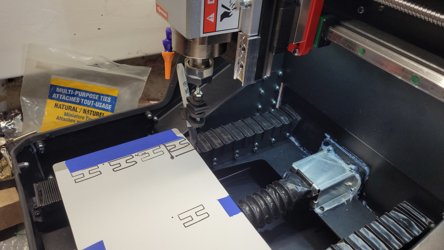
Here a small and really simple G-code program I wrote to make the letter H in capital with a pen :
; PURPOSE OF THIS IS TO LEARN and UDERTSTAND GCODE
; PROBABLY NOT THE BEST AND FAST GCODE
;
; #####################################################################
; #
; # DO NOT RUN THIS GCODE ON YOUR CNC WITHOUT CHECKING THE GCODE
; # BE SURE TO UNDERSTAND WHAT IS DOING
; # YOU CAN CRASH YOUR CNC
; # OR WORSE
; # YOU CAN SERIOUSLY DAMAGE OR BREAK YOUR CNC
; #
; # I CANNOT BE HELD RESPONSIBLE IN ANY WAY IN THE EVENT OF A PROBLEM
; # OR DAMAGE TO YOU OR YOUR CNC
; # THIS IS EDUCATIONAL PURPOSE ONLY
; #
; #####################################################################
;
; _ _
; | | | |
; | | | |
; | |_| |
; | _ |
; | | | |
; | | | |
; |_| |_|
;
G15 G40 G49 G80
;G21 = set unit set to mm
G17 G21 G64 G90
; FISRT MAKE Zero ALL AXIS
;H letter
; Rapid move to the starting position of the H letter, with the tool 2.032mm above the workpiece (X=0, Y=6.35, Z=2.032)
G0 X0 Y6.35 Z2.032
G1 Z0 F10 ; go to coordinate at feed rate 10 mm/min and Z0 touch the paper
Y38.1 F600 ; move tool along Y+ at feed rate 600 mm/min first part of the H
X6.35 ;Move the tool 6.35mm in the positive X-direction (creating the horizontal bar of the H)
Y25.4 ; Move the tool 25.4mm in the negative Y-direction
X12.7 ; Move the tool 12.7mm in the positive X-direction
Y38.1 ; Move the tool 38.1mm in the positive Y-direction
X19.05 ; Move the tool 19.05mm in the positive X-direction
Y6.35 ; Move the tool 6.35mm in the negative Y-direction
X12.7 ; Move the tool 12.7mm in the negative X-direction
Y19.05 ; Move the tool 19.05mm in the negative Y-direction
X6.35 ; Move the tool 6.35mm in the negative X-direction
Y6.35 ; Move the tool to the starting Y-position of the H letter
X0
Z2.032 ; Rapid move the tool back to a safe height above the workpiece (Z=2.032mm)
M30 ; End the program and rewind the CNC machine to its starting position
NOTE : This is just an example and you should consult your CNC machine's manual for specific instructions on how to program it.
Probably not the best G-Code but it's OK on my machine :