Experimentation : extracting firmware from cheap wifi router
26 janvier 2025
I bought years ago a really cheap wifi router, obviously made in Chi... The router was avalaible in Canada for a few dollars, an excellent candidat for learning how to extract a firmware from this kind of hardware.
I chose the cheap one because this was my first test and I'm not an electronician and there's is a good chance I'll make a mistake and destroy the router. Learning and experimenting is OK, but not for too many dollars at the beginning.
Information about this wifi router
model wr1410
HW VFer : 1.0
input 12V 500mA
Default SSID : kisslink_35B2
MAC : 4C:6E:6E:97:35:B2
SN :C06C000357
default ip : 192.168.1.1
default user/passwd : admin
All this information are directly avalaible on the router.
PCB exploration
First I look for a serial port or something similar on the motherboard of the router and thanks to the indications on the PCB I found a good candidate.
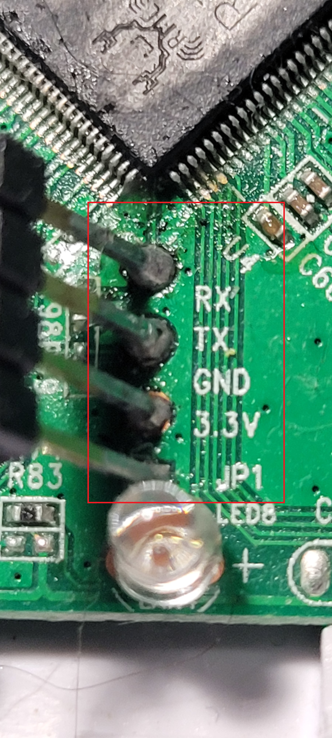
PCB Soldering
After having identified the 3 pins on the pcb thanks to the perfectly clear indications RX TX 3.3v it is enought to solder 3 pins directly on the pcb. Some flux, some soldering paste and this is ready to solder the 3 pins. Nothing complicated.

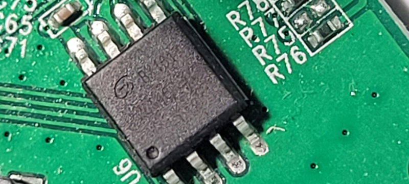
SPI Flash chip
I make several photos, changing light, adjusting zoom and finally I get a readable photo and find the type of the spi flash chip. This an 25Q16CSIG.

With that info we can hope to find information about this chip on internet, we need the specifications to be sure we have the correct pins and in particular the pin one on the chip. The chip is made GigaDevice, the package is GD25 with 8 pins, the pin 1 is marqued by a small round hole in corner of the chip. The pdf with all the spec for this component can be found on internet.
Tools and software to read the SP Flash chip
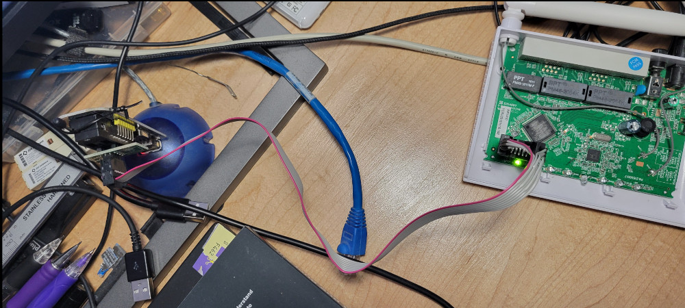
It's time to take the tools that will allow you to read the firmware directly on the pcb. This tools is usb to ttl serial adapter module, it can do more but this is not really the point. The price for this usb to ttl serial adapter module is ridiculous for the work it does.

It is important to understand that this is a somewhat special clamp and that it must be correctly installed to have good contact between the clamp and the pins of the chip. I had to start 3 times before I managed to place the clamp correctly and be able to read the entire SPI Flash with the flashrom tools.
The command used to read the SPI Flash with flashroom was :
userf@devpc:~/Data/Data/Doc/Doc_Kisslink/Firmware/flashrom -V --programmer ch341a_spi -r test_4.bin
To be sure I read the firmware I run this command 4 times and compare the sha1sum, I hope that if I have the same sum 4 times my bin file is complete and without corruption.
userf@devpc:~/Data/Data/Doc/Doc_Kisslink/Firmware$ sha1sum test*
f2023b8636303ae7d11bb0dc37164abe20823df3 test_1.bin
f2023b8636303ae7d11bb0dc37164abe20823df3 test_2.bin
f2023b8636303ae7d11bb0dc37164abe20823df3 test_3.bin
f2023b8636303ae7d11bb0dc37164abe20823df3 test_4.bin
userf@devpc:~/Data/Data/Doc/Doc_Kisslink/Firmware
And voilà
Final note
There are other tools to do this job but they are usually very expensive and often require unsoldering the SPI Flash Chip but in return it has a greater capacity to read different brand of SPI Flash chip and increase the reliability of the reading as well as the speed.
Next part: Maybe analysis of the firmware.