Go back
Change settings for the vfd and spindle on the DMC2_Mini
14 July 2025
Problem : spindle start from mach3 but doesn't accelerate and finally stop
Required : Spindle and Vfd Doc and time...
ATTENTION ATTENTION
IF YOU ARE NOT CONFORTABLE TO MAKE THIS CHANGES AND SETTINGS IT'S BETTER TO CALL AN ELECTRICIAN
IN CASE OF PROBLEM refer to the VFD and spindle documentation. This settings are ok with my spindle and vfd but cannot set for your case your vfd or your spindle.
Assembly is now completed and spindle start from the software Mach3 but doesn't accelarate and finally stop.
After some mails with the company, I have to change some settings in the VFD.
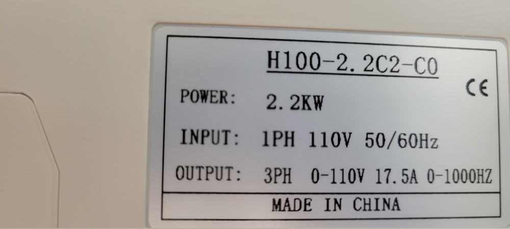
The VFD is a chinese VFD a H100-2.2C2-C0
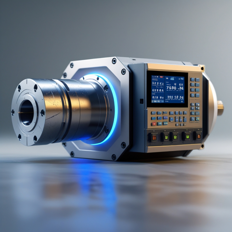
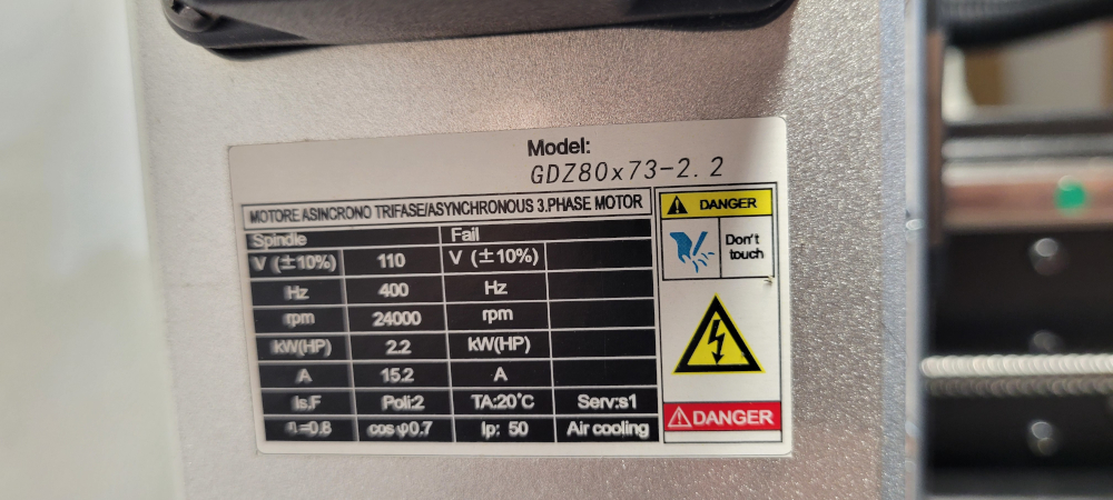
the spindle is also a chinese spindle a GDZ80x73-2.2 110V
VFD Cables

For the spindle behaviour this is most likely because the VFD settings are not all correct. This is common with the white 110v vfd. Check the following settings in particular this settings : F004 F005 F006 F007 F008 F009 F010 F011 F014 F015 F041 F143 F144
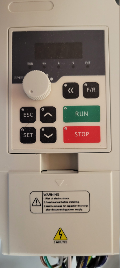
To set the vfd it's really simple, on panel press set and change for the desired value and use the button with the arrow up or down to change the value when you get the correct value press set again and the button esc. When it's done simply remove the main power on the machine and vfd wait the wait completly shutoff and replug all power and go back to check the settings.
BE CAREFULL INCORRECT SETTING CAN DESTROY THE VFD OR THE SPINDLE OR BOTH CHECK THE VFD DOC IF YOUR ARE NOT CONFORTABLE TO MAKE THIS CHANGES IN THE VFD CALL AN ELECTRICIAN
IN CASE OF PROBLEM refer to the VFD documentation. This settings are ok with my spindle and vfd but cannot set for your case your vfd or your spindle.
Set the breakout board to control the spindle
F001 1 breakout board input, control from sfotware like linux cnc or Mach3
default value = 0 is the keypad of the vfd
F002 1 breakout board input frequency setting selection 1 mean Al1 pin AL1 (AnalogInput number 1, pwm voltage) in the vfd panel connector probably
*F004 : reference frequency must be set to 400
*F004 400 set it to 400.0
*F005 400 set it to 400.0
*F006 01.0
*F007 000.5 ok set it to 000.5
*F008 : 110 motor voltage, default setting is 220.0, must be change to 110.0
*F009 12.6 set it to 12.6
*F010 3.0 set to 03.0
*F011 000.5 set it to 000.5
*F014 10
*F015 10
F023 reverse prohibit (0 = reverse prohibit, 1 = reverse allow) default value is 1, if your spindle cannot do reverse must be set to 0. Check the doc of your spindle
*F041 06
F044 FOR(X1)function : set to 2 mean to forward
F070 input channel selection for analog quantity, set to "0" mean 0-10v, set to "1" mean 0-5v for my case must be set to "0" (0-10v) probably controlled via Al1 pin AL1 (AnalogInput number 1, pwm voltage)
F072 Al1 channel gain (0.0 ~ 500 %)
*F143 2
*F144 0024
F170 : selection of extension display 1 default = 4 display bus voltage for testing set it to 02 = display operation speed, show the rpm of the spindle, can required additional changes
UNPLUG THAN REPLUG to make sure everything is ok and test the spindle with a gcode commad :
S12000M3 (tell to the spindle to run at 12000rpm)
try to start and stop the spindle from mach3 and test accelaration
Now I have a nice spindle that run at 23856 rpm.
Next step calibrating the probe...